What does this have to do with computer repairs? Well, it doesn’t, technically, but I am also a casual ham radio operator and recently the VHF/UHF final transistor in my radio blew.
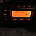
So what happened? I bought a 2 meter amplifier off of eBay and while I was testing it my radio stopped triggering the amp. I measured the power output from my Yaesu FT-857D and it showed less than 1 watt on 2 meters even though it was set to 50 watts in the menu. On 440 MHz, it showed less than 3 watts output. HF output was fine.
I knew that I needed a new VHF/UHF final output transistor but I have never replaced one before and didn’t know where to get it from. I also found that two different RF output transistors were used with this radio (2SC3102 and RD70HVF1) and the circuit design was different for each. Luckily the FT-857D is very easy to open, so I pulled the top off and pulled the bottom case off and found that the final output transistor is easy to get to. (It is on the bottom.)
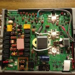
The three white things toward the right side are output transistors. The one in the middle is the HF final output transistor and the one at the top is the VHF/UHF final. Silk screened on the board is 2SC3102 for the VHF/UHF transistor and 2SC5125 for the HF/6 meter transistor. The exciter doesn’t have thermal paste on it (the one at the bottom) where the other two do. This paste conceals a temperature sensor for the finals and is easy to remove and reuse.
Since I knew that I needed the 2SC3102, I ordered it here and it arrived in about a week and a half. http://www.utsource.net/ic-datasheet/2SC3102-597398.html
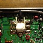
Replacing the HF final transistor is easier than the VHF/UHF transistor because of the surface mount components soldered across the tabs.
This was my first experience working with surface mounted components, so I didn’t have a good plan for how to remove them. I heated up the tabs, sucked out the solder, and they came loose! Speaking of sucking solder, you’re going to need three soldering irons for this job: something with a lot of heat to heat up the entire tab, something that can suck old solder off, and a fine pencil for soldering the surface mount components back.
I couldn’t remove the green components on the left side until I was able to remove the transistor. Once it was out, I carefully removed them. For installing the new transistor, tin the leads first, place the transistor in the correct location and use the screws to align it but don’t tighten them! Heat up each of the tabs with plenty of heat and “squish” the solder out beneath the tabs as it heats up. Hold it down with another tool until the solder cools. Do this for each tab so the transistor is seated properly. This is critical because the transistor is mounted to heat sink and has thermal paste on the backside. It needs to be almost touching the heat sink without the screws tightened. Otherwise you risk damaging it when you tighten those screws.
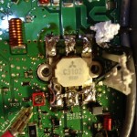
Once all of the tabs are securely soldered, use your pencil iron to solder the surface mount components. Place them with tweezers or a tiny pair of needle nose pliers. I found that I could apply pressure using a jewelers screwdriver. Heat up just enough solder to secure these components. One end at a time. I had to add a little solder to make a good joint.
My messy soldering job:
So does it work? It does! I now have 50 watts output on 2 meters and 20 watts on UHF.

